Leave Your Message

What Is a Die Casting Part and How Is It Made?

A Die Casting Part is a metal component formed by forcing molten alloy into a reusable steel mold. The process creates detailed shapes with impressive repeatability. Common materials include aluminum, zinc, and magnesium alloys. These metals support lightweight housings, brackets, covers, handles, and automotive components.

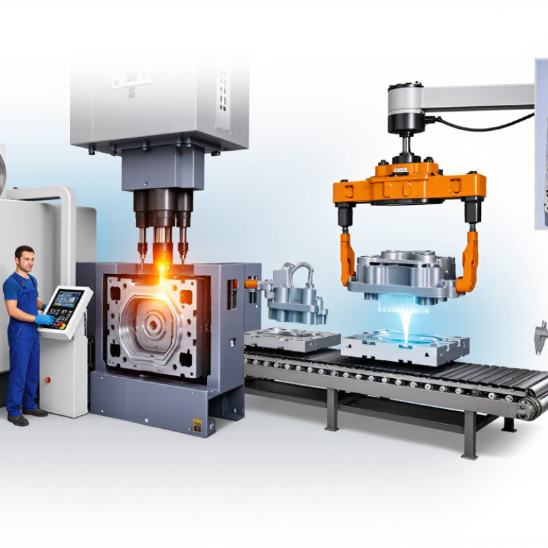
The process begins with mold preparation and alloy melting. Operators check temperature, lubrication, and machine settings before injection. Then, hydraulic pressure drives the molten metal into the closed die. The metal fills narrow ribs, holes, and textured surfaces within seconds. After cooling, ejector pins release the casting. Trimming removes runners, gates, and unwanted flash. Some parts receive drilling, machining, coating, or surface finishing.

Small variations matter. A slight temperature change can affect filling, shrinkage, or surface quality. Poor venting may trap air inside the casting. That problem is easy to miss. Quality teams often use visual checks, dimensional measurements, and additional testing when performance is critical. Reliable manufacturers also trace alloy batches, mold maintenance, and inspection results.

This article explains how a Die Casting Part moves from design to finished component. It examines mold construction, injection pressure, cooling behavior, finishing steps, and quality control. The explanation reflects practical manufacturing principles, but real production conditions differ. Design assumptions sometimes fail. Careful testing remains necessary. A technically attractive part may still require redesign if it cannot release cleanly from the die or withstand service loads. Understanding these limits helps engineers, buyers, and manufacturers choose the process with greater confidence.

What Is a Die Casting Part and How Is It Made?

What Is a Die Casting Part?

What Is a Die Casting Part and How Is It Made?

What Is a Die Casting Part?

A die casting part is a metal component formed inside a reusable steel mold called a die. Manufacturers usually use aluminum, zinc, or magnesium alloys. The alloy is melted, injected under pressure, and cooled into the die’s cavity. This process creates detailed shapes with consistent dimensions.

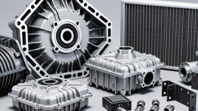
A die-cast part may include a motor housing, heat sink, bracket, or structural cover. Its surface can show a fine parting line, gate mark, or small ejector-pin marks. These details are normal, not automatically defects.

The International Aluminium Institute reported global primary aluminum production above 70 million metric tons in 2023. That supply supports aluminum die casting across transportation, electronics, and industrial equipment. The U.S. Department of Energy also identifies lightweight aluminum components as a practical way to reduce vehicle mass and energy use.

Manufacturing starts with die design and alloy selection. Engineers check wall thickness, draft angles, cooling channels, and expected loads. Molten metal then enters the die quickly. After solidification, ejector pins release the part. Workers trim excess metal and inspect critical areas. Not every part leaves the machine perfectly. Porosity, distortion, or incomplete filling can still appear.

Tips: Keep wall thickness as uniform as possible. Add draft for easier ejection. Ask for X-ray or pressure testing when internal porosity could affect safety. NADCA’s Product Specification Standards provide useful guidance for tolerances, surface conditions, and inspection planning. But real production results can vary with tooling age, alloy chemistry, and machine settings.

Which Materials and Designs Are Used in Die Casting?

A die casting part is a metal component formed inside a reusable steel die. Molten alloy enters the cavity under high pressure and fills fine features quickly. Material choice affects weight, strength, corrosion resistance, heat flow, and finishing costs.

Aluminum alloys suit housings, brackets, and heat-sensitive structures because they combine low weight with good thermal conductivity.

Zinc alloys support thin sections and detailed surfaces, although they increase part weight.

Magnesium alloys reduce mass further, but they require careful handling and strict process control.

Copper alloys provide excellent electrical and thermal performance, yet their higher melting temperatures demand specialized equipment and die materials.

Design decisions often determine whether production remains stable.

Maintain fairly uniform wall thickness to reduce shrinkage and internal stress.

Thin walls cool quickly.

Add draft angles so the casting releases without scraping the die surface.

Rounded corners, ribs, and smooth transitions improve strength while limiting sharp stress points.

Gates should guide metal into the cavity without trapping excessive air.

Ejector pins need strong, accessible surfaces, not delicate cosmetic areas.

One common mistake is copying a machined design directly into a die. That approach may create deep pockets, trapped air, or difficult tooling.

A better review examines filling simulation, cooling channels, tolerances, and expected loads before cutting the die.

Perfect uniformity is not always practical. A small wall variation may be acceptable when performance, cost, and tool life are considered together.

Human judgment still matters.

How Is a Die Casting Part Made Step by Step?

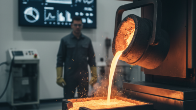
A die casting part begins with a carefully designed steel die. Engineers review the part’s shape, wall thickness, draft angles, and likely shrinkage. The selected alloy is then melted in a controlled furnace. Temperature matters. If the metal is too cold, it may fill the cavity unevenly. If it is too hot, defects and die wear can increase.

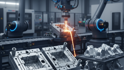
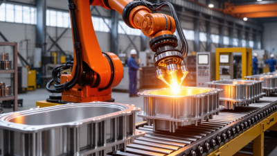
The operator applies a release agent and closes the die under high clamping force. Molten metal is injected rapidly into the cavity, filling narrow ribs and detailed surfaces. Pressure remains briefly while the metal solidifies. The die then opens, and ejector pins remove the casting. Sprues, runners, and overflow material are trimmed away with cutting tools or automated equipment. The cycle can be fast, but it is not careless.

The finished part is cleaned and inspected. Technicians may check dimensions with gauges, measure surface quality, and examine internal porosity when the application requires it. Small vents and cooling channels often influence the result more than expected. The first shot is rarely perfect. A slight flash, incomplete fill, or trapped air may require adjustments to pressure, temperature, or die alignment. Experienced teams record these changes and compare each batch against approved specifications. Powder coating, machining, or other finishing work may follow, depending on the part’s function.

What Is a Die Casting Part and How Is It Made? — How Is a Die Casting Part Made Step by Step?
Step Process Stage What Happens Typical Materials, Temperatures, or Conditions Main Result and Quality Check
1 Part Design and Feasibility Review Engineers define the part geometry, wall thickness, draft angles, ribs, bosses, fillets, and functional tolerances. The design is reviewed for filling, solidification, ejection, and machining requirements. Die-cast aluminum walls are commonly designed around approximately 1.5–3.0 mm where the geometry and alloy permit. Draft angles are generally added to surfaces that must release from the die. A manufacturable 3D model is created. The review checks for sharp corners, isolated thick sections, insufficient draft, difficult undercuts, and nonuniform wall thickness.
2 Alloy Selection A metal alloy is selected according to strength, corrosion resistance, thermal conductivity, weight, surface finish, and operating temperature. Common die-casting alloys include aluminum, zinc, and magnesium alloys. Aluminum alloys are widely used for lightweight structural and general-purpose parts; zinc alloys are suitable for detailed, thin-walled components. The chosen alloy must meet the required mechanical, dimensional, corrosion, and finishing specifications. Chemical composition is verified before production.
3 Die Design and Tool Making A reusable steel die is designed with cavity inserts, cores, runners, gates, overflows, vents, cooling channels, and ejector components. The die is machined, assembled, and tested. Die components are commonly made from hot-work tool steels because the tool is exposed to repeated thermal cycling, pressure, abrasion, and molten metal. The completed die must match the approved part model. Dimensional inspection, cavity alignment, moving-component travel, and cooling-channel integrity are checked.
4 Die Preparation The die is cleaned, installed in the die-casting machine, preheated, and sprayed with a controlled release lubricant. The two die halves are then closed and clamped. Preheating reduces thermal shock and helps stabilize filling. Die lubricants assist release, reduce friction, and help control die-surface temperature. The die should be free of debris and excessive lubricant. Proper clamping prevents flash caused by die separation during injection.
5 Metal Melting and Preparation Alloy ingots or approved returns are melted in a furnace. The molten metal is checked for temperature and may be treated to reduce oxides, inclusions, and dissolved gas. Approximate pouring or holding temperatures vary by alloy and process. Aluminum die-casting melts are often handled around 660–750°C; zinc alloys are commonly handled around 400–450°C. The melt should have the correct chemical composition and temperature, with minimized oxide contamination and gas content. Sampling and spectrometric checks may be used.
6 Metal Metering or Ladling A measured quantity of molten metal is transferred into the shot sleeve or injection chamber. The amount must be sufficient to fill the cavity, runner system, overflow, and biscuit. The charge size is calculated from the net part mass plus the casting-system mass and process allowance. Transfer time is kept short to limit temperature loss and oxidation. Correct dosing helps prevent short shots, excessive flash, and unstable shot conditions. The transfer system is checked for cleanliness and repeatability.
7 Injection and Cavity Filling The plunger pushes molten metal through the runner and gate system into the closed die. Die casting uses high injection pressure and controlled plunger movement to fill detailed cavities rapidly. High-pressure die casting commonly uses injection pressures of approximately 30–150 MPa, depending on the alloy, machine, part geometry, and process design. Filling time is often measured in milliseconds. The cavity should fill without cold shuts, misruns, air entrapment, or excessive turbulence. Process sensors may record plunger position, speed, pressure, and cavity conditions.
8 Pressure Intensification and Solidification After the cavity is filled, pressure is maintained or intensified while the metal solidifies. This compensates for shrinkage and improves contact between the metal and die surfaces. Intensification pressure and hold time are adjusted according to alloy, wall thickness, gate design, and thermal conditions. Cooling channels remove heat from the die in a controlled manner. Correct pressure and cooling reduce shrinkage porosity, sink-related defects, distortion, and inconsistent dimensions. The casting must solidify sufficiently before ejection.
9 Die Opening and Ejection Once the casting has cooled enough, the die opens and ejector pins remove the casting from the moving die half. The runner, gate, overflow, and biscuit remain attached. Ejection timing depends on part size, alloy, wall thickness, die temperature, and cooling efficiency. Ejector force must be high enough for release but low enough to avoid deformation. The part should release without sticking, cracking, bending, ejector-pin damage, or unacceptable marks. Die surfaces and vents are checked before the next cycle.
10 Trimming and Deflashing Excess metal from the runner, gate, overflow, and parting line is removed using a trim die, saw, press, machining operation, or manual finishing method. The trimming method is selected based on production volume, alloy, component geometry, and allowable edge condition. Parting-line flash limits are defined on the drawing. The casting achieves the required outline and edge condition. Operators inspect for remaining flash, over-trimming, cracks, bent features, and damage near functional surfaces.
11 Secondary Machining Critical holes, threads, sealing faces, datum surfaces, and precision features are machined when the as-cast condition cannot meet the required tolerance or surface finish. CNC milling, drilling, tapping, reaming, turning, and other processes may be used. Machining allowances are included in the die-cast design where required. Machined features are checked for dimensional accuracy, position, thread condition, flatness, perpendicularity, and surface finish according to the product drawing.
12 Surface Finishing The casting may be cleaned, polished, shot blasted, tumbled, painted, powder coated, anodized, plated, or conversion-coated depending on appearance and performance requirements. Finishing selection depends on alloy compatibility, corrosion exposure, electrical requirements, wear resistance, color, and target surface appearance. The finished surface is checked for color consistency, adhesion, coating thickness, stains, scratches, exposed metal, roughness, and cosmetic defects.
13 Inspection and Testing Finished parts are inspected using visual checks, dimensional measurement, gauges, coordinate measuring equipment, leak testing, hardness testing, or internal-defect inspection when required. Inspection criteria are established from the engineering drawing, control plan, sampling plan, and applicable material or industry requirements. X-ray or computed tomography can reveal internal porosity. Parts are accepted, reworked, or rejected based on documented criteria. Typical defect checks include porosity, cracks, cold shuts, inclusions, flash, distortion, and dimensional variation.
14 Cleaning, Packaging, and Traceability Approved parts are cleaned, counted, protected against damage, and packed for storage or shipment. Production records link parts to alloy batches, die identification, and process conditions. Packaging materials and separators are selected to prevent scratches, corrosion, contamination, and deformation during handling and transportation. The final product conforms to specifications and remains protected until use. Traceability records support quality investigations, process control, and repeat production.

How Are Die Cast Parts Trimmed, Finished, and Inspected?

A die casting part leaves the mold with extra metal around its edges. Trimming removes the runner, gate, overflow, and visible flash. Hydraulic presses, saws, or precision cutters may perform this operation. The chosen method depends on the alloy, part geometry, and production volume. Experienced technicians check cutting tools often because dull edges can distort thin walls. Edges matter. Small burrs remain.

After trimming, the part may receive shot blasting, tumbling, grinding, or vibratory finishing. These processes remove sharp fragments and improve surface consistency. Some parts require drilling, tapping, reaming, or light machining for accurate assembly. A clean surface also helps coatings bond more reliably. However, aggressive finishing can erase small design features or reduce critical dimensions. That risk deserves attention.

Inspection normally combines visual checks with measurement. Operators look for cracks, cold shuts, dents, trapped particles, and incomplete filling. Calipers, gauges, coordinate measuring equipment, and leak-testing tools can verify dimensional and functional requirements. Inspection records should identify the part, measurement point, tool, and result. Not every defect is obvious. A smooth surface can hide internal porosity, while a minor mark may have no functional effect. Experienced inspectors compare findings with approved drawings and realistic tolerances. Even careful processes need review because trimming pressure, tool wear, and temperature changes can create variation.

Where Are Die Casting Parts Commonly Used?

What Is a Die Casting Part and How Is It Made?

Die casting parts are common wherever metal components must be light, accurate, and produced quickly. Automotive manufacturers use them for transmission housings, motor covers, steering parts, and structural brackets. The International Aluminium Institute reported that transport consumed about 26% of global aluminium demand in 2022. That demand supports wider use of aluminium die casting in vehicles.

Consumer electronics also depend on die casting. Thin camera frames, laptop hinges, heat sinks, and appliance housings need smooth surfaces and stable dimensions. The Grand View Research Die Casting Market Report estimated the global market at approximately 79 billion U.S. dollars in 2023. It also identified transportation and electronics as major application areas. These parts usually begin with a steel mold. Molten aluminium, zinc, or magnesium is injected under high pressure. After cooling, workers trim flash, inspect dimensions, and apply finishing treatments.

Industrial equipment uses larger castings for pump bodies, gear cases, and automation frames. Their internal passages can reduce assembly work. However, die casting is not perfect. Porosity, trapped air, and mold wear can still cause failures. In my experience, a visually clean surface does not prove structural reliability. X-ray inspection, dimensional checks, and process records matter. Reported market growth is useful, but it can hide differences between alloys, part sizes, and production regions.

What Is a Die Casting Part and How Is It Made?

Die casting parts are metal components produced by injecting molten metal into a reusable steel mold under high pressure. The process creates accurate, detailed parts with smooth surfaces and consistent dimensions.

Typical material use: Aluminum is widely used for lightweight automotive and electronic housings, zinc is suitable for detailed hardware and small components, magnesium is chosen when very low weight is important, and copper alloys are used where high strength and thermal or electrical conductivity are required.